Diesel Duck 382

Diesel Duck 382
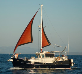
Diesel Duck 382 with the "get home" steadying sails up.

Wednesday, March 29, 2017

Keep on keeping on

We keep moving forward.  I heard saying somewhere about boat building and it went something like: Building a boat is not a hard job, it's the fact that there are a million different jobs to do that make it difficult.  I'm beginning to see how true that is.  I have not encountered anything that is particularly difficult to do but my mind is always filled with the thought of all the jobs that need to be done.  The only way to overcome this is to keep working on something, anything, just keep checking boxes off the list.

We took the transom knee out of the clamps and laid our patterns for both knees out on them.  I used a wide tipped marker to trace the patterns on to the blank knee lamination's for the stem and transom. Using the thick marker created a thick line to cut out.  I cut out the outside of the line leaving the inner edge of the line for final fitting once the keel is ready to receive them.


I was lucky to have a 10 1/4" timber saw to cut them out with.  A standard 7 1/4" circular saw would not have enough depth to make the cut.  As it was I had to mark the pattern on each side of the blanks and cut both sides in order to get through these 7" thick pieces.  I thought about cutting them on my bandsaw but that proved to difficult.  Not only are these knees quite large and heavy and difficult to manipulate on the bandsaw but the cutting would need to proceed very slowly.


Now I hate when I watch a home show or a building show and the builder pulls out some obscure tool that no average woodworker or DIY enthusiast would own and uses it to make a job look easy.  I was fortunate to have been given this timber saw by a retired construction worker friend of my fathers.  If you are attempting something similar you could use a chainsaw or rent a timber saw from a tool rental place.  These saws are big, powerful and have a ton of torque so they take some getting use to.  I've only used this saw a couple of times but I was basically familiar with how it feels when cutting.  If you end up using one I would recommend a few practice cuts before getting started.

Once that job was completed we moved out to the boat shed to build another frame.  This time it was for station 10.  We installed our spacer blocks on the lines we lofted out on our framing table to account for the thickness of the hull planking.  Just like station 2, we laid out our timbers, marked our lines and cut out the angles.


 I again used cardboard to create a pattern for the gussets and cut them from 3/4" ACX plywood.  I cut my patterns exactly in the shape of the joint and add the shoulder of the gusset once I lay out the pattern on the plywood.  I just use a straight edge to connect the inside corners of the pattern.  You can check out our building videos on YouTube to see a better illustration of the process.


Station 10 still has a relatively steep bevel angle but I was able to use the same pattern for both sides of the frame.  Just like station 2, we screwed the gussets to the timbers to temporarily hold them together until we are ready for glue and bolts.


It takes about an hour to machine up and cut all the bevels on the timbers and then it takes about an hour to complete the assembly process.  The work went pretty smoothly this time and as other readers and viewers have said, the process is speeding up as I become more familiar with what is required.


I was grateful to pick up an overtime shift this weekend so I only had one weekend day to work but I think I made the most of it.  As more and more friends and family find out about the project I'm getting use to the strange looks and offers for psychological help.  Every once and a while I do have moments of panic thinking about what I have gotten myself into, but It really has been an enjoyable process so far.  I look forward to my time in the shop all week long and so far I have no regrets.

Thanks for following along and we love to hear from our readers and viewers so don't hesitate to send us a message using the link above.  If you prefer you can email us at contact@seadreamerproject.com or leave a comment here or on YouTube.  Hopefully we can bang out a couple more stations this weekend and get ready to loft out more stations.

Monday, March 20, 2017

If you build it.


I brought my A-game (I think) and successfully laid out five frames at stations 2, 10, 18, 26 and 34.  I did another time lapse of my work day if you would like to see a quick review.


Everything went really well and it was actually kind of enjoyable.  I can't stress enough that this requires patience and attention to detail.  I literally double checked every measurement before getting the markers out.  I also learned that there really is no way around the lines being close together, particularly on the bottom portion.  If it becomes a concern going forward, the only solution would be to lay out fewer frames and paint over more frequently.  We will see and I'll keep you advised.

With the frames laid out it was time to make some saw dust.  Before I powered up the machines I took some measurements from the framing table to determine how long to rough cut the pieces to. Since I purchased my lumber in the rough it had to be surfaced prior to use.  I feel very comfortable with this portion of the job as I have been surfacing and squaring up stock for many years.  I gave my jointer and planer a good work out and prepared my stock quickly.

I located the frame bevels from the plans provided by Mr. Buehler and used my table saw to make those cuts.  I also cut some 3/4" plywood blocks the width of the finished boat planking.  These blocks are used to set the timbers back from the lines on the lofting equal to the thickness of the planking so the finished boat comes out the same size as the designer intended.

I screwed the blocking to the framing table, two for the side and two for the bottom, right on the lofting lines and laid out my machined timbers.  Station 2 has particularly steep angle that the side piece meets the bottom.  the side piece is beveled to the angle of the slope of the bottom of the boat and the bottom timber butt's up to the side piece.  Unfortunately I did not take into account how steep that angle was and I ended up cutting my side pieces to short.  So I gathered up two more rough boards the correct length, machined them up, cut the bevels and tried again.

Lofting for five stations with blocking in place for station 2.

I then laid out my timbers against the blocking so I could transfer the angles I would need to make the cuts on in order to get the pieces to meet correctly.


Nothing complicated here, just making sure everything was on their lines and transferring the angles to the lumber.  Once I had my marks I cut the timbers out with my circular saw.  I then put my cut timbers back on the table and used cardboard to create templates for the gussets. Because the angle is so steep for the bevels at station 2 I needed to make templates for both the front and back of the frames.  I then took the cardboard templates and traced them out on to some 3/4" ACX plywood and cut them with my circular saw.


I drove a 3" wood screw through the edge of the bottom piece and into the side piece from the inside of the frame near the chine.  This pulled the joint together nicely for the application of the gusset. The gussets were then just laid on and screwed temporarily into place.  two screws on the side member and 2 on the bottom member.  I then flipped the assembly over and put gussets on the other side. When we get some warmer temperatures I will take this apart and apply some Weldwood plastic resin glue to the joint and reattach the gussets.  Howeve,r once glued, I will bolt the gusset to the frames instead of using screws.


The final step was to attach some temporary bracing to the assembly to hold it in place until it is attached to the keel.  One down, 18 to go!

It was a busy weekend of boat building and although I only got one frame done I was happy with the progress.  I also got my work shop up to temperature and epoxied the stem knee together.  Once that fully cures we'll put our thinking caps on and try to figure out the best way to cut both the stem and transom knees to shape.

If you want to keep up with the daily happenings of the Sea Dreamer Project please be sure to check out our Facebook page and click on the "like" button to get regular updates.  Thanks for following along and fingers crossed for some warmer weather.

Tuesday, March 7, 2017

Lofting frames: Connect the dots carefully

To spin this past weekend in a positive light, I'll say that it was a great practice run.  I got started lofting the frames on our framing table.  Essentially you use the measurements from table of off-sets to plot out the various points for the chine, sheer and raised sheer (aft end) and then connect the dots. If you think of your framing table as a sheet of graph paper with an X and Y axis it's a little easier to understand.

The table of off-sets has the heights above the base line and the half widths.  You simply take the measurements for the designated part of the boat, at a specific station, from each part of the table of off-sets and plot them out on the framing table.  After you connect all the dots you'll have a representation of the boat frame for which the measurements came from.

It's important to note that these lines represent the outside of the hull.  When actually building the frames you need to set the timbers for the frame back from this line the distance that equals the thickness of your hull.

Station 26

I started with station 26.  I chose 26 because it was the largest frame and the first frame with the raised sheer.  Doing this one first would ensure that my lofting table was big enough.  Things went really well and this frame came out perfect.

The only challenging aspect of the process is doing mathematics in this peculiar boat building measurement format of Feet, Inches and 8th's of inches.  The math comes in to play when you subtract the height of the rabbet from all the other measurements.

Subtracting the rabbet is required because you don't want to have to draw out the size of the entire keel on your framing table.  This allows you to keep the size of your framing table manageable.  The process begins by laying out the thickness of your keel in the center of the framing table along your base line. You need to be precise.  If your keel is seven inches wide then you need to measure out 3 1/2 inches from the center line.   The bottom of these marks will act as the new baseline without having to draw out the entire keel.  In order to remove the keel you must subtract the height of the rabbet from the other measurements.  This allows you to use the bottom of your framing table as the base line instead of the arbitrary base line provided in the profile view.

I'm not going to get into it to much here, you can read Georges book for a much better explanation than I could ever give or you can check out Episode 7 of the Sea Dreamer Project on YouTube for a video tutorial.  In sum and substance you must subtract 12 inches from the feet measurement and added it back in to the other measurements in inches and 8th's of inches before you do the math.  However this is only required when necessary to do the mathematics and avoid negative integers.  In some cases you'll be able to just line up the 3 measurements for each point and do the simple math that will give you your final measurement.

The simple way will be obvious when you see it, for example;  lets say you want to subtract 3-3-4 from 5-5-4. Well if you try to convert 5-5-4 as described in Georges book you get 4-16-12.  When you attempt to subtract 3-3-4 from 4-16-12 you get 1-13-8.  Remember the 8 represents 8th's of inches, so if you have 8 8's that equals 1 inch so you would add that into the inch column and your 8th's column becomes zero.  The inch column then becomes 14, which is over a foot.  By subtracting 12 inches and adding that back into the foot column you get 2 feet 2 inches and 0 8th's or 2-2-0.  If you were to have just lined up the 2 original measurements, like in the good old fashion math way, you could just have subtracted each column and gotten the same answer.  You'll only need to convert the measurements as described in the book when you have a situation like trying to subtract 2-11-5 from 5-2-4.  You quickly see that your going to need to borrow from another column to avoid negative integers and that indicates you must convert the measurement by subtracting a foot from the foot column and add those 12 inches back into the inches and 8th's of inches column.

It sounds way worse than it is, and if you read Georges book and practice a few times it quickly becomes very clear.

My problems occurred when I accidentally used measurements from two different stations.  I was using a piece of paper to cover the columns I was not using for the express purpose of avoiding confusion.  However I was just not being careful enough and accidentally moved the papers to the wrong station and that sent everything to hell.  I quickly noticed my error when the station I was working on was not a mirror image of itself.  Unfortunately I had already drawn in the lines in marker.  I felt that I could not make the changes and draw in new lines and still have each station be clearly observable.  So I painted over it all and will try again.

The pictures below are where I stopped before painting over.  You can see the size and scale of this boat very clearly.  You can also get an understanding of the process of connecting the dots.


My 6' tall son giving scale to the picture.
My overall impressions are that this is a time consuming process, but not difficult.  You need to have rigid attention to detail and double check each measurement before drawing the lines in.

Additionally, when I start over, I am going to spread out the stations out more.  I started doing stations 26, 28, 30 and 32.  However, as a I drew them in, the bottom planking lines overlapped each other very closely.  Not really a big problem but I don't want to give myself an opportunity to make a mistake by being confused by lines that are so close together. I was using different colored markers for each station but still, the possibility for error is to great, at least for me.

So next time I'm going to start with stations 2, 8, 16, 24 and 38.  Each station is very different in size so I think they will be more clear to the eye.  Once each frame is assembled I'll paint over the table in white paint and lay out stations 4, 10, 18, 26...etc. repeating the process until all the frames are built.

I set up my Ipad to do a time lapse of my work day and have posted it here.


Thanks for checking out our project, hopefully next time I'll be able to report some success lofting the frames.

Be sure to check out our Sea Dreamer Project YouTube channel,  as we'll be having a little give away contest posted soon to thank everyone for putting us over 200 subscribers.  I know it's not much in the grand scheme of YouTube, but hey, it's a start!

Wednesday, March 1, 2017

A prop shaft runs through it


We had a very nice vacation but I was eager to get back to the shop.  Our flight home was very early so after arriving, making a quick trip to the grocery store and grabbing lunch, I was back working on our project by noon.  It's been an unusually warm winter here in upstate NY and on the day we arrived home it was close to 60 degrees.  I decided to take advantage of the warm weather and try to address the condensation issue in the boat shed.  I added gable vents to the East and West sides of the shed.  Install was simple with a circular saw and a multi-tool.  I secured it with a few screws.  So far, so good but I'll need to check on a really cold day to see if its actually making a difference.


I then got started on dadoing out the grooves in each half of the chine log.  Each half required a 1 3/8" deep by 2 3/4" wide groove cut from the very center of each.  I did this on my table saw with a stacked dado head cutter.  I set up a  5/8" stack and cut the full depth of 1 3/8" in a single pass.  This is a lot to ask of your table saw, so if you have anything other than a 3hp saw you'll need to make multiple passes working up to the final depth.  Once the dado's were cut, I cleaned up each groove with a hand plane and then applied two coats of epoxy to waterproof the wood.


The next step was to glue up the chine log to its final dimension.  I chose to use resorcinol glue again as this piece will live the majority of its life underwater and I wanted to use a completely waterproof adhesive.  The most forward section of the chine log will be through bolted to the keel so that will add some additional holding power to assure it never comes apart.  It's the belt and suspenders approach to building that I am a big fan of.


The glue up went smoothly, and like the previous glue up, I used several clamps at very high pressure.  Once it was set in clamps, I ran a long batten down the inside of the newly formed chine log and scraped the glue squeeze out from each side, just to clean it up a bit.  The finished dimension of the shaft log is 2 3/4" by 2 3/4".


I tried to be a little more judicious in my use of adhesive in order to minimize the amount of squeeze out and it worked out well.

A few days later I un-clamped the assembly and brought it out to the boat shed to make room for the next glue up.  The stem and transom knees were next and were quite simple.  I simply laid out my patterns that I made on the red rosin paper and began cutting 2x8's and stacking them, cut to the length that covered the pattern.

I marked each with a reference line so I could ensure repeatability when I did the glue up.  For many of the keel components I am choosing to use epoxy.  There is no perfect adhesive but epoxy comes darn close.  It's strong, easy to work with, sets up in a wide variety of temperatures and is nearly water proof.  However it does have its weaknesses.  It starts to loose strength at temperatures over 120 degrees (depending on manufacture) and it is not rated to be completely waterproof.  

In this application where these keel components should never be submerged (I hope) and should not be subjected to high temperatures, like pieces on deck in direct sunlight, epoxy will be an excellent adhesive.  Additionally, these knees will be bolted to the various keel components they are designed to support.  Belt and suspenders again.

I mixed up batches of epoxy as I went and applied the adhesive to each face of the pieces to be joined.  Epoxy only requires moderate clamping pressure, so I only applied pressure up to the point where squeeze out began to appear and the joint appeared closed around the entire piece.


I had to clamp up in sub-assemblies in order to keep them within the limits of my table saw to be cut to their final width.  I ran out of epoxy and clamps to do the second knee so that will have to wait.

Next up was preparing the framing table for lofting our frames.  I set up a straight edge along the base of the table with some scrap plywood in order to have a clean edge to catch my tape measures.  I joined each edge of the plywood so it was perfectly straight and then cut a parallel edge on the table saw.  I also used more scrap plywood on each side of the table, perpendicular to the base line.  These will act as clean, straight edges to hook my chalk line to.  Again, I joined one side and cut a parallel edge on the table saw.  I was careful to ensure the side pieces were exactly 90 degrees to the base line.


I then went ahead and laid out half of station 26 using the table of off-sets. If you click on the picture above you can see the lines that I laid out.  I'll get into the specifics of laying out the frames next time.  If you want a sneak peek of that process you can check out season 1, episode 7 on our YouTube channel that will be online Saturday March 4, 2017.

We've had over 15,000 views to the site since October and we are grateful for all the support.  Please check out our YouTube series by following the link at the top of the page or by clicking HERE.  If you have questions or comments don't hesitate to let us know.  You can send us a message on the link at the top of this page or email us at contact@seadreamerproject.com

Thanks again and we'll see you next time.