
Welcome to the Sea Dreamer Project! This is the story of a complete boat building novice and his family with no previous nautical experience constructing a 41 foot Diesel Duck in the backyard of an Upstate New York home. This George Buehler designed trawler yacht is a blue water cruiser designed to cross oceans. Built mostly of home center lumber, epoxy and galvanized hardware, this boat is within the reach of an average person. It's the internet boat project for the rest of us!
Diesel Duck 382
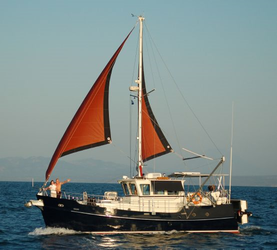
Diesel Duck 382 with the "get home" steadying sails up.
Friday, December 28, 2018
Monday, December 17, 2018
Decisions, decisions
We left off in our last post with 5 stations left to install. If you've been keeping up with us on social media and YouTube, you know the last of the stations have been installed and we've moved on to the bilge stringers.
However, due to pure neglect and laziness, I have not kept up with all the other stuff we've been working on. Let's get all caught up!
As we approached station 26 I began to strongly consider installing our engine. This would have been the easiest time to get it in while everything was wide open. Because of my inexperience I wanted to have the full bulkhead that the plans indicated for station 26 in place so I could get the most accurate measurements for the engine setup.
Before we started framing the bulkhead with gusto, we needed to ensure each previous frame was square to the keel. In order to hold them square we would need some temporary bracing to hold them in position. In order to hold that bracing firmly in position we needed the transom to be as stiff as possible. That required the transom to get it's first layer of planking. As I've said before, boat building is systems built on systems.
Once again, the simple design of the Diesel Ducks makes transom planking very straight forward. In order to make things a bit safer and easier to work on we attached a walking platform to the back wall of the boat shed. Once that was done, we started by milling up our rough cut, white oak lumber. The planks were machined to between 4 and 5 inches wide and 3/4" thick. We used full length pieces that spanned the entire width of the transom and let them overhang each side. Each plank was installed with #14, 1 1/2" galvanized, cut thread wood screws. Additionally each plank was glued with epoxy below the waterline and Titebond III above the water line.

The only part of the planking that required any scribing, was the curved top portion. This was just a matter of dry fitting a board to the frame and then tracing the curve onto the board. We then made our cuts on the bandsaw and installed as normal. Once all the transom boards were installed we used our circular saw to cut off the overhangs, flush with the sides of each frame.

With the planking complete on the transom, we moved on to squaring each frame. This was accomplished with careful measurements from the chine on each side of the boat to the centerline of the keel. Pine strapping was screwed to each frame to hold things in position. We added strapping near the chine and the sheer. This was a bit time consuming but it will have the added benefit of keeping things rock solid when we move on to planking the rest of the boat.
Before we could start building the framing to support our bulkhead we needed to install the deck beam for station 26. This required us to build our deck beams ahead of schedule. The deck beams are curved to provide an adequate crown to the deck so water easily runs off. Instead of cutting the crown from a single piece of a long, very wide board that would result in a lot of waste and would be difficult to replicate, exactly for each station, we decided to laminate our deck beams from 3/4" stock.
We started by building a bending jig that long strips of the 3/4" white oak could be bent around. I felt fairly comfortable with this process, as it was nearly identical to the process we used to build the arches for our boat shed. Using what I learned from that project, I built a very robust bending jig comprised of 2 layers of 3/4" OSB glued together coupled with large stop blocks epoxied and screwed to the OSB.
The dimensions of the curve of each deck beam are indicated in the plans. It was a simple matter of laying out the measurements, springing a batten around the curve and then tracing the batten. Once that was established the stop blocks were attached along the line.
 |
| Laminated deck beam bending jig |
We machined up all of the white oak we bought that was designated for the deck beams. I figured while we were at it, we might as well build most of the deck beams right now. This is definitely a two man job and once again, I called on my father to help out. The process is pretty simple and 3/4" white oak bends quite easily without steaming or wetting.


Each deck beam consisted of 5 layers, glued with Titebond III. We applied the glue to all the layers and then bent and stacked them up on the jig. We used several clamps to pull the lamination into the stop blocks and then additional clamps along the arc to pull things together. While still attached to the jig, several 3 1/2", #10 coated deck screws were driven through the entire assembly. The clamps on the stop blocks were then removed, leaving the remaining clamps in place and the whole assembly was moved to another spot in the shop to cure.

After 48 hours I removed the remaining clamps and moved forward with installation at station 26. I used our rolling gantry crane to hold the deck beam in position after it was cut to length. The beam was installed on it's marks with 2 galvanized carriage bolts on each side after wood preservative and bedding compound were applied.

This is another one of the times where bolt building can be simultaneously fun and challenging. There are no directions in the plans on how to build the bulkheads. This requires each builder to come up with their own plan. It took a few days of thinking while I worked on other things to come up with my plan.
Trying to think ahead to how this bulkhead, which divides the state room from the engine room, would act in the finished boat, I decided I needed to add some additional framing. In order to bring the sides and bottom frames into co-planer with the deck beam, I added some beefy spacers to each location with epoxy and screws. These pieces overlapped the joint between the sides and bottoms adding some additional strength.
Then we added some framing to the area between each side to support the 2 layers of 3/4" plywood that would span this area. Since the space is around 12 feet, a single piece of plywood could not span the full length. Once we move on to installing the plywood we will overlap the seams to eliminate any weak spots.
The center framing was notched to fit against the floor timber and deck beam while also being co-planer with the spacers we added to bottom and side framing. This allows for co-planer surfaces on both sides of the bulkhead for easy installation of insulation and wall material to keep things strong and tidy looking.

This is a difficult process for me to describe in words, It might be easier to check out our YouTube building series to see all the details.
Not that any of this was a waste of time, but after all was said and done, for various reasons, I decided not to install the engine at this point. I continued on with frame setting as we discussed in the previous post.

This brings us almost up to date with where we are in the build as of this writing. In our next post we'll talk about the keel cheeks that needed to be installed before we could move on to the bilge stringers.
Thanks for checking out our project and we always love hearing from people, so don't hesitate to comments, send us a message or shoot us an email.
I hope everyone has a safe and fun holiday season.
Subscribe to:
Posts (Atom)